The Toro Clock Project


Latest News

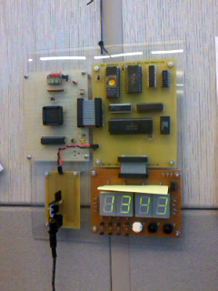
2012/12/05 -- Check out the fully-functional clock which now hangs on my office wall.
2011/09/09 -- A DS1620 3-wire temperature sensor has been added to the clock. A short video of the new feature is available
2011/07/18 -- After the addition of pushbuttons for time setting, my TORO processor has begun its new life as a timekeeper. I'm in the process of moving everything over from Google Sites to here, so please forgive broken links and bad HTML.

2011/04/25 -- Wow. Time flies, but the good news is that fixing an errant chip select on the MC6822 was the key to all my display woes. New videos are available in the Tidbits area. More details to follow...

2010/07/21 -- TORO clock counts seconds! I'm not doing digit decoding right now, so it just makes funky shapes on the LED displays. Check out the movie in the Tidbits area!
(there are still some issues with the 6822 IIA acting flakey. With all segments on, it's sinking 80mA.. might need to go to discrete NPNs for segment drive)

Background

Back in 1997, I was attending Kansas State University and pursuing a Computer Engineering degree. One of the required courses in the curriculum was EECE643 "Computer Engineering Design Lab", where were were to design and implement a simple 8-bit microprocessor in programmable logic.

We'd be working in teams of two.. except that there were an odd number of students in the class. I'd previously taken courses with the instructor, Dr. John Devore, and he asked me if I'd be ok with working on my own. I was really excited to finally get some "hands-on" time with real hardware (theory only takes you so far).

The task: Implement the "TORO" 8-bit processor in programmable array logic. Dr. Devore would provide us the specification, but we were to come up with internal implementation on our own. Additionally, we were given three implementation options. The first was to use 5 PALCE22V10s. Dr. Devore assured us that our design was virtually guaranteed to fit. The second option was to use only 4 22V10s and "work really hard to make it fit". If successful, we would receive extra credit (my memory is a bit fuzzy what that meant). Finally, we had the option to use the more complex MACH211 device, which was essentially 4 22V10s in one 44-pin PLCC.  This path would also qualify for extra credit.

Given my inherently lazy nature, I decided I didn't want to wire all those chips together and picked the MACH211 option. This choice would let me keep all the control logic internal, or so I thought.

Everything went well as the weeks passed, until I got a cryptic error one day indicating "product terms exceeded" from PALASM. Being new to programmable logic, I tried in vain for days to reduce logic terms and get my %!@# design to fit. Eventually, I gave up and asked Dr. Devore if I could use an additional 22V10 for control logic. As I recall, he hadn't implemented this in the '211 and was sympathetic to my plight.

Finally, with more wiring and the extra 22V10 in place, I performed initial bring-up. Everything looked good .. no shorts in power/ground, no excessive current indicating outputs fighting each other. It was time to plug my processor into the RAM / ROM / I/O board. There was only one such board, and we were given opportunities to test our designs during lab. The I/O board was wired up to a VT100 terminal and would run a simple program of Dr. Devore's design to exercise the CPU.

The 24-pin bus between my CPU and Dr. Devore's board was attached and power applied. While I was happy that the VT100 terminal spat out something that looked like the test program output, it was apparent that something was wrong. The test program would write out a few characters, then appear to restart and do it all over again. I don't recall how we found the solution, but Dr. Devore suggested that I add bypass caps to my design. In my haste, I hadn't put down the "standard issue" 100nF caps for power bypass.

Once the new bypass caps were in place, the CPU ran like a champ! From what I can recall, the test program asked for your name and a number, then proceeded to print out "Hello <name>" the specified number of times.

A Dusty Drawer

Fast-foward 13 years and I'm working for a semiconductor company in Dallas, TX as a software engineer. Most of the time, I'm writing some bit of software, but I occasionally get to dig into hardware design to help track down design bugs in our processors.

One day, while cleaning out a drawer in my study, I find my old TORO CPU board, still wrapped in its protective anti-static bag. Thinking back on my times at KSU, I wonder if I could get it going again and make it do something useful; I decided to make TORO into a wall clock, complete with 1.5" tall green LED 7-segment displays.

TORO - The Processor

TORO is pretty limited, but that adds to the challenge!
Instructions are decoded by the 22V10 and drive control signals into the MACH211, where the accumulator, ALU, and program counter live. The 22V10 also generates a 3-bit instruction clock from the system clock which is used to sequence memory access and ALU operations.

Instruction Format

        76543210
        OOQQMM--

        OO = Operation Class    QQ = Qualifier  |       MM = Addressing Mode
                                                |      
        00 Load                 X0 Normal       |       00 Immediate
                                X1 Complement   |       01 Direct
        01 Store                XX Normal       |       10 Indirect
        10 ALU                  X0 Add         
                                X1 And
        11 Branch               00 Always
                                01 C
                                10 N
                                11 Z


The TORO Clock

I began by constructing an memory and I/O board to replace the board which was originally part of Dr. Devore's setup. This board also supplies the system clock, which runs at 32.768 kHz and drives a binary counter which divides the clock by 32768. This is convenient, as it provides me with a 1 pulse per second output. I'm using the Maxim (nee Dallas Semiconductor, my employer) DS32KHZ Temperature-Compensated Crystal Oscillator as the clock source, for stability reasons.

The address and data busses are multiplexed, so a 74LS273 was required to latch the address. The lazy-man's approach was taken and the '273 latches address data on every falling clock.

Since I needed RAM, ROM, and some I/O to live in the memory map, I used PALCE20V8 to decode the address. The PAL also performs a bank-switch function. Any write to the 0xF_ addresses will use the lower four data bus bits to select one of 16 ROM banks.

Memory is decoded as follows:
As an aside on the MC6822 IIA, which is a cousin of the MC6821 PIA (pain in the ???): The IIA requires some screwy interfacing when connected to TORO. Originally, I thought I could simply use it as any other I/O chip I've seen. I was wrong-- The chip select line has very little to do with the output enable for this device. Instead, signals are referenced to the E clock signal. Address and data are latched on the rising edge of E, and output drivers are switched off shortly after E clock falls. Additionally, 80ns of setup time before E is required of /CS in order for the 6822 to play nicely. Finally, if you want the interrupt flags to work right, you have to provide E clocks while /CS is de-asserted. This is not immediately clear from the data sheet, and drove me batty for a week until I re-read the paragraph detailing the "conditioning of the edge-sense network".

The MC6822 is an open-drain version of the MC6821, and can sink up to 10mA per pin (subject to power dissipation limits).

I use a small "trampoline" routine in RAM to change ROM banks. TORO has no native CALL/RETURN (or even a stack for that matter), so two RAM locations hold the desired bank and return address. I have a macro in my assembler which synthesizes a page switch this way.

Current progress

The memory and I/O board is nearly complete. TORO can run programs stored in ROM, read/write RAM, and exercise the IIA's port pins. I currently have a simple program counting the 1-second clock ticks and incrementing PA0-PA7.

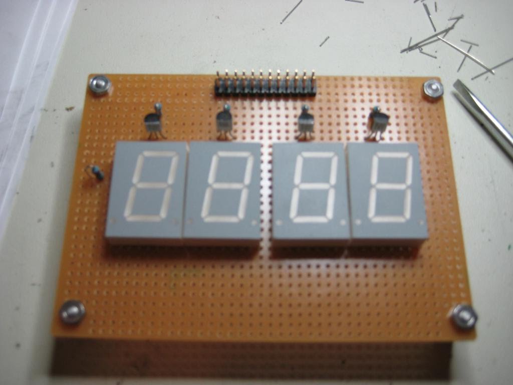
The LED display board is currently in work, but should be complete soon.

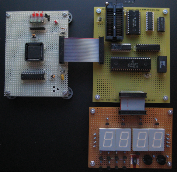
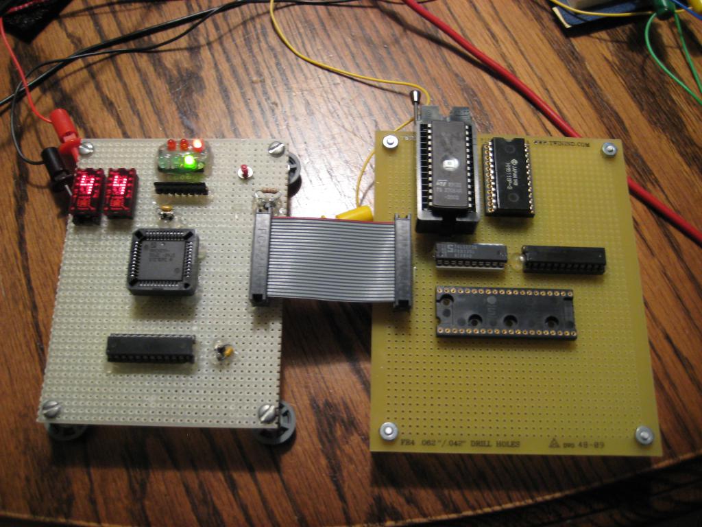
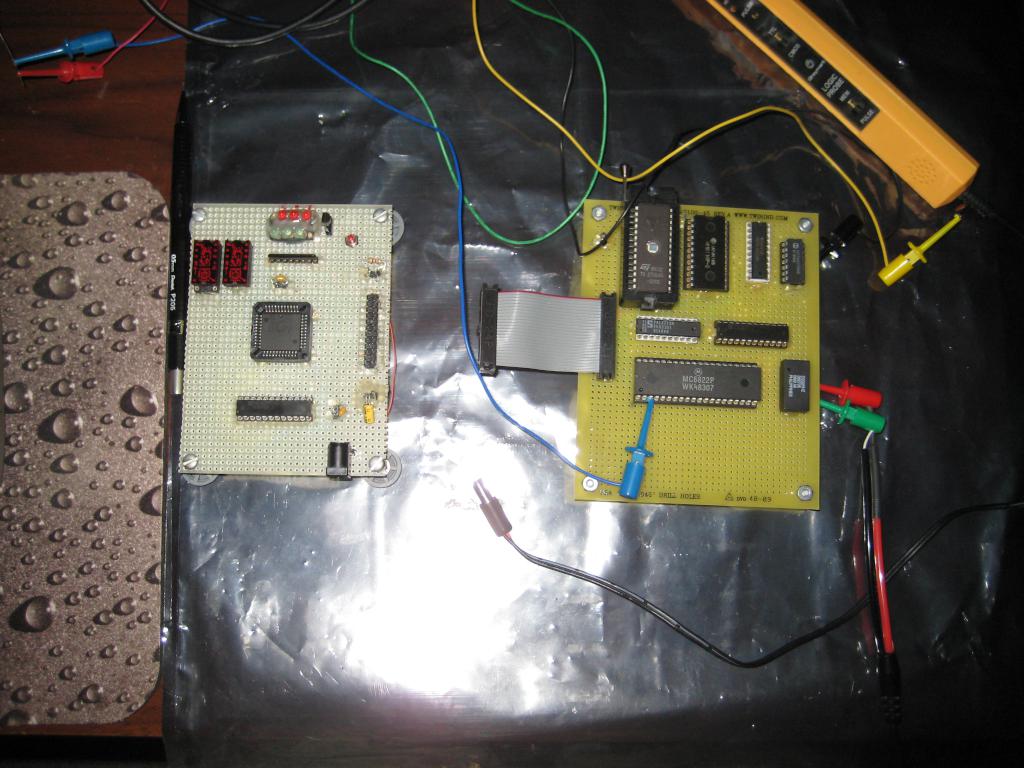
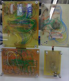
A few pictures of TORO in various stages of completion:

TORO starts to live after getting ROM, RAM, and address decoding wired up on the daughterboard.
The TIL311 hexadecimal displays were added to debug the design. Green LEDs show the instruction cycle timer, while red LEDs show ALU carry, zero, and negative.
(Those TIL311s get HOT! I estimate around 200mA for the both of them)


The daughterboard is now fully populated with system clock & RTC generation (DS32KHZ and 74LV8154) and the MC6822 IIA


The LED display board is partially complete. The displays are common-anode, so PNP transistors are used for digit select (top).
Two pushbuttons, HOUR and MINUTE, will be routed into the '6822 IIA interrupt inputs to detect time-setting presses.

In the Tidbits area, you can find a short video of TORO running a test program.

Go to the Homebrew CPU homepage for others who have homebrewed CPUs!