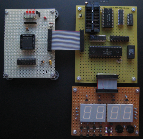
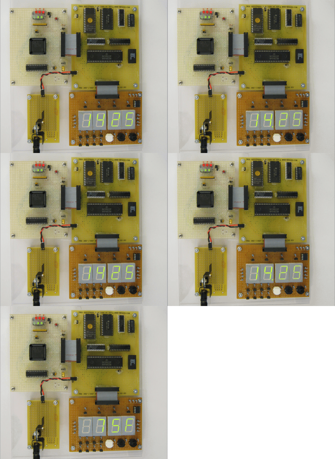
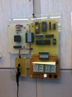
2012/12/05 -- Check out the fully-functional clock which now hangs on my office wall.
2011/09/09 -- A DS1620 3-wire temperature sensor has been added to the clock. A
short video of the new feature is available
2011/07/18 -- After the addition of pushbuttons for time setting, my TORO processor has begun its new life as a timekeeper. I'm in the process of moving everything over from Google Sites to here, so please forgive broken links and bad HTML.
2011/04/25 -- Wow. Time flies, but the good news is that fixing an errant chip select on the MC6822 was the key to all my display woes. New videos are available in the Tidbits area. More details to follow...
2010/07/21 -- TORO clock counts seconds! I'm not doing digit decoding right now, so it just makes funky shapes on the LED displays. Check out the movie in the
Tidbits area!
(there are still some issues with the 6822 IIA acting flakey. With all segments on, it's sinking 80mA.. might need to go to discrete NPNs for segment drive)
I began by constructing an memory and I/O board to replace the board which was originally part of Dr. Devore's setup. This board also supplies the system clock, which runs at 32.768 kHz and drives a binary counter which divides the clock by 32768. This is convenient, as it provides me with a 1 pulse per second output. I'm using the Maxim (nee Dallas Semiconductor, my employer) DS32KHZ Temperature-Compensated Crystal Oscillator as the clock source, for stability reasons.
The address and data busses are multiplexed, so a 74LS273 was required to latch the address. The lazy-man's approach was taken and the '273 latches address data on every falling clock.
Since I needed RAM, ROM, and some I/O to live in the memory map, I used PALCE20V8 to decode the address. The PAL also performs a bank-switch function. Any write to the 0xF_ addresses will use the lower four data bus bits to select one of 16 ROM banks.
Memory is decoded as follows:
- 0x00 - 0xBF ROM (depends on bank switch bits from 20V8, initially all zeroes)
- 0xC0 - 0xDF RAM
- 0xE0 - 0xEF MC6822 Industrial Interface Adapter (IIA) .. salvaged this from a dead TRS-80 and had been in my parts bin forever
- 0xF0 - 0xFF Bank Switch
As an aside on the MC6822 IIA, which is a cousin of the MC6821 PIA (pain in the ???): The IIA requires some screwy interfacing when connected to TORO. Originally, I thought I could simply use it as any other I/O chip I've seen. I was wrong-- The chip select line has very little to do with the output enable for this device. Instead, signals are referenced to the E clock signal. Address and data are latched on the rising edge of E, and output drivers are switched off shortly after E clock falls. Additionally, 80ns of setup time before E is required of /CS in order for the 6822 to play nicely. Finally, if you want the interrupt flags to work right, you have to provide E clocks while /CS is de-asserted. This is not immediately clear from the data sheet, and drove me batty for a week until I re-read the paragraph detailing the "conditioning of the edge-sense network".
The MC6822 is an open-drain version of the MC6821, and can sink up to 10mA per pin (subject to power dissipation limits).
I use a small "trampoline" routine in RAM to change ROM banks. TORO has no native CALL/RETURN (or even a stack for that matter), so two RAM locations hold the desired bank and return address. I have a macro in my assembler which synthesizes a page switch this way.
Current progress
The memory and I/O board is nearly complete. TORO can run programs stored in ROM, read/write RAM, and exercise the IIA's port pins. I currently have a simple program counting the 1-second clock ticks and incrementing PA0-PA7.
The LED display board is currently in work, but should be complete soon.
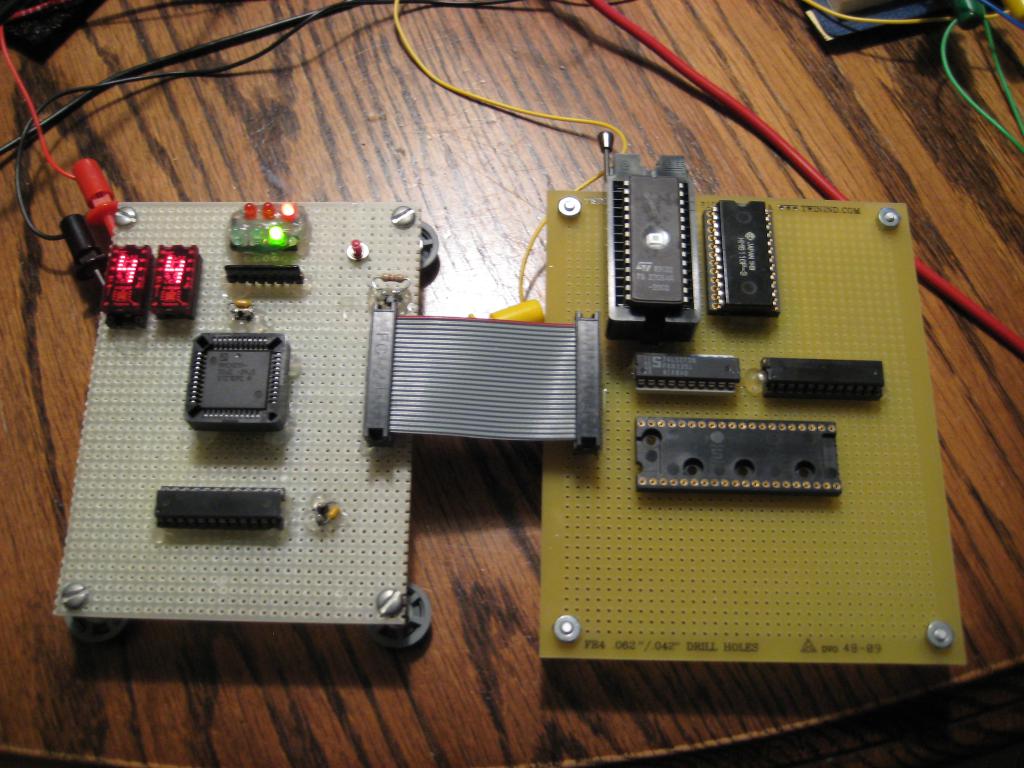
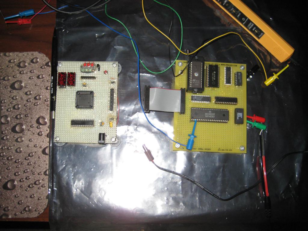
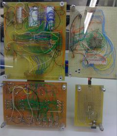
A few pictures of TORO in various stages of completion:
TORO starts to live after getting ROM, RAM, and address decoding wired up on the daughterboard.
The TIL311 hexadecimal displays were added to debug the design. Green LEDs show the instruction cycle timer, while red LEDs show ALU carry, zero, and negative.
(Those TIL311s get HOT! I estimate around 200mA for the both of them)
The daughterboard is now fully populated with system clock & RTC generation (DS32KHZ and 74LV8154) and the MC6822 IIA
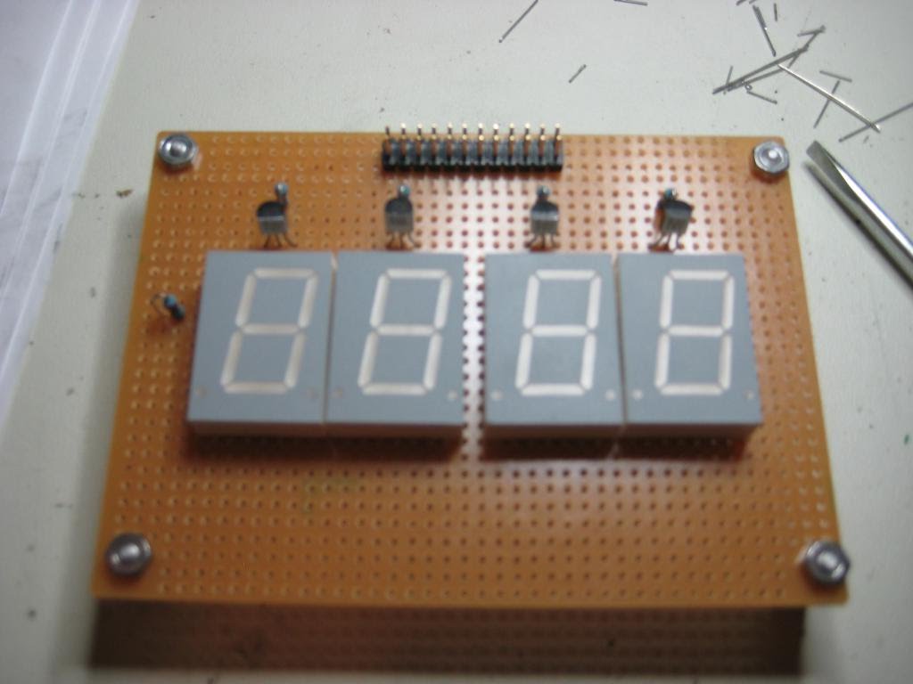
The LED display board is partially complete. The displays are common-anode, so PNP transistors are used for digit select (top).
Two pushbuttons, HOUR and MINUTE, will be routed into the '6822 IIA interrupt inputs to detect time-setting presses.
In the
Tidbits area, you can find a short video of TORO running a test program.
